


The Wire and the Flange of the Dampers
This article provides a practical guide for regulating the dampers of grand pianos. It explains the role of different wire curves and the damper support wire, and describes a detailed procedure for correcting the most common problems that may occur during regulation. The article will be useful for technicians specializing in piano maintenance and repair, as well as anyone interested in understanding the internal mechanics of these instruments.
This article is based on the writings of Jack Krefting, a technical expert of the PTG. The text provides valuable and informative information on the subject matter, and it is emphasized that the article is based on the author's personal experience. It should be noted that the opinions expressed in the article are personal and do not in any way bind Danny L. Boone or other individuals mentioned in the texts used for the writing of this article.
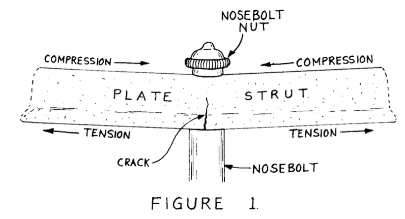
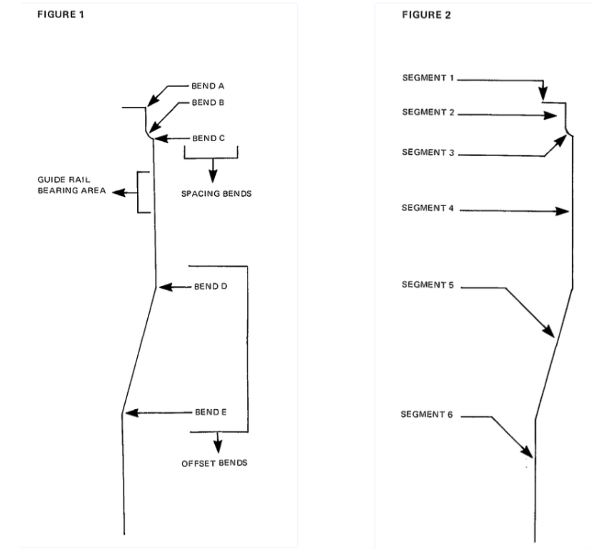
In Figure 1, we see that the wire has five bends. The only exception would be when there is no offset (guide rail hole directly above underlever), in which case the wire would only be bent at points A, B, and C.
The top bend (A) is made when the wire is installed and should not be altered during subsequent regulation. Segment 1 (see Figure 2) is imbedded in the hole in the damper head, and segment 2 should always remain in its mortise. All side-to-side spacing and tipping of the damper head should be done by altering the angle of bends B and C. The angle of segment 3 will depend on the amount of spacing required to center the damper head over the unison.
Similarly, the angle of segment 5 is determined by the amount of offset. The angle of bends D and E must be identical, and wire segments 4 and 6 must be parallel. If they are not, either the damper head will travel to one side or the wire will exert side pressure on the underlever top flange, causing stuggishness. This is the most common error made in damper regulation, but it is also the easiest problem to correct once the technician realizes what he must do.
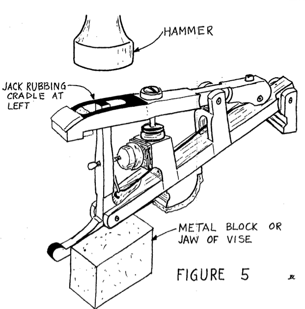
To fully understand the principle, let's examine the purpose of these two all-important bends. The sole function of bend E is to make segment 6 parallel with the hole in the underlever top flange. To test this, place the damper in position with the screw loose. Now depress the damper pedal and watch the damper head. It should not move; rather, the underlever top flange should move up and down freely on the wire with the movement of the pedal. The technician then can be certain that no side pressure is being exerted on the flange.
Sometimes the wire fits too tightly, so that even if bend E is correct, the flange still will not slip over the wire. If this is the case, check the bottom of the wire for a burr caused by a wire cutter. File it smooth and try again. There might also be a distortion of the wire at the point where the screw contacted the wire. Straighten the wire at that point and remove any burrs. If it still won't fit easily, the wire diameter must be reduced slightly. I use a piece of fine emery cloth for this purpose, and find that it doesn't take much reducing to get a nice, free fit in the flange.
The sole function of bend D is to make the damper move straight upward. If the head travels to either side, bend D is the culprit. If the head moves up without traveling
but the wire bears against one side of the guide rail bushing, then bend D is at the right angle but in the wrong place. In the middle or treble, for instance, if the wire bears to the right, then bend D is too high on the wire. Another way of correcting this would be to slightly lessen the angle of both
bends, but if bend E is altered at all it must be rechecked for freedom of movement in the flange. When the wire is bent so that the head moves straight up and down without bearing on one side of the guide rail bushing, with a free (unstressed) underlever top flange, bends D and E are correct.
To space the head from side to side, I suggest the following procedure which I learned a long time ago from Cliff Geers. Assuming a treble damper must be moved toward the bass, grasp the head with a smoothjawed damper plier and bend the head over to the right to about a 45-degree angle, bending the wire at point B. The plier should be covering wire segment 2 during this bending operation to ensure that the wire cannot bend at point A. Next, from under the pinblock, bend the wire at point C to the left until the head is square with its neighbors and parallel to the strings in the unison.
The result of all this will be that the head has moved to the left because the angle of bends B and C has been increased, and wire segment 3 is now leaning further toward the bass. Unfortunately, this also has the effect of shortening the length of the wire, which means the screw must be loosened and the underlever reengaged at a slightly lower point on segment 6. If the head had been i:noved to the right, the wire would have become slightly longer, and the underlever would then have to be raised slightly. Naturally, all this must be reversed in the bass because the wires are mounted on the opposite side of the damper heads.
If the head is tipped in a fore-andaft direction so that both ends of the damper do not contact the strings simultaneously, the wire must be bent in the proper direction at point B. Please note that point B is the only point on the entire wire that could require a compound bend (bends in two different planes). We will get into this area further in another issue when we discuss the type and thickness of felt to be used.
If the damper head is twisted, the natural reaction of the inexperienced technician would be to loosen the screw, align the head, and retighten the screw. This is nearly impossible to do, especially if the screw is determined to align itself with its former niche in the wire. The head twists out of alignment again when the screw is tightened. So, instead of going to all that trouble, we should twist the wire itself, leaving the screw tight. Grasp the wire in an ordinary serrated-jaw plier just above the flange and twist until the head is in alignment with the strings. Naturally, this procedure is only used when there is a minor twist, not when the head is 30 degrees out of line. The wire is soft and malleable to a point, but when that point is exceeded it will break.
If it does, don't panic. Ask the housewife for a new damper wire, while pointing to the coat closet. Four or five different gauges of soft wire are used in making coat hangers, and with a little luck you can find one of the proper diameter. Cut and bend a piece of it to dimensions and you're back in business. I know it sounds like a Mickey Mouse repair, but wire is wire; so long as it's unpainted and of the right gauge, it'll work just fine in an emergency.
Next month in this space we'll discuss underlevers and their related parts.
What's Your Reaction?